Next: 6.2.5 Extraction Lens Up: 6.2 Experimental Previous: 6.2.3 Conversion Surfaces Contents
Expected secondary electron yields of a conversion surface are in
the range of 0![]() 1 electrons per incident particle in the
energy range under investigation (10
1 electrons per incident particle in the
energy range under investigation (10![]() 1000eV per atom).
Since these electrons might interfere with the measurement of negative
ions a deflection magnet was built which would cause a magnetic field
perpendicular to the incoming neutral particle beam and parallel to
the surface. It was decided that the gyro radius of a low energy electron
(E
1000eV per atom).
Since these electrons might interfere with the measurement of negative
ions a deflection magnet was built which would cause a magnetic field
perpendicular to the incoming neutral particle beam and parallel to
the surface. It was decided that the gyro radius of a low energy electron
(E ![]() 2eV) next to the surface should be of the order
of 1mm whereas oxygen atoms with an energy of
2eV) next to the surface should be of the order
of 1mm whereas oxygen atoms with an energy of ![]() 200eV
should not be deflected at all. The necessary strength of the field
is calculated by
200eV
should not be deflected at all. The necessary strength of the field
is calculated by
where ![]() denotes the electron mass,
denotes the electron mass, ![]() the energy
of the electron,
the energy
of the electron, ![]() the elementary charge,
the elementary charge, ![]() the gyro
radius, and
the gyro
radius, and ![]() the magnetic flux density.
the magnetic flux density.
The necessary flux density ![]() computes to 3.3 mT. At this flux
density protons and oxygen atoms are only marginally deflected. For
the dimensioning of the magnet a simple approach giving a field of
the right order of magnitude was chosen. For an electro-magnet with
an iron core, and a small air gap with a moderate and approximately
homogeneous field in the air gap the magnetic resistivity
computes to 3.3 mT. At this flux
density protons and oxygen atoms are only marginally deflected. For
the dimensioning of the magnet a simple approach giving a field of
the right order of magnitude was chosen. For an electro-magnet with
an iron core, and a small air gap with a moderate and approximately
homogeneous field in the air gap the magnetic resistivity ![]() is defined by
is defined by
where ![]() is the total magnetic flux,
is the total magnetic flux, ![]() the current
in the coil, and
the current
in the coil, and ![]() the number of turns on the coil. The magnetic
resistivity may be written as the sum of the resistivity of the iron
core and the resistivity of the air gap:
the number of turns on the coil. The magnetic
resistivity may be written as the sum of the resistivity of the iron
core and the resistivity of the air gap:
| (6.7) |
| (6.9) |
With the mechanical dimensions of the magnet a magnetomotive force
![]() = 67A was calculated. A copper wire with 0.3 mm diameter
was used for the coil yielding four layers of wire within the available
space and a total of 300 turns. The total resistance
= 67A was calculated. A copper wire with 0.3 mm diameter
was used for the coil yielding four layers of wire within the available
space and a total of 300 turns. The total resistance ![]() is calculated
by
is calculated
by
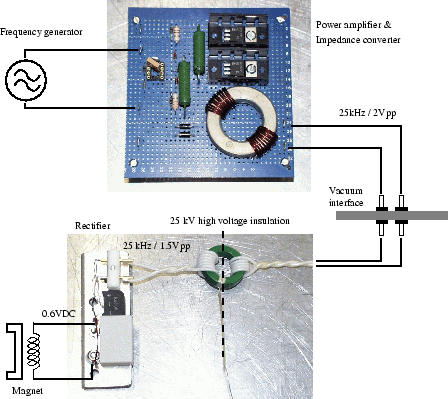
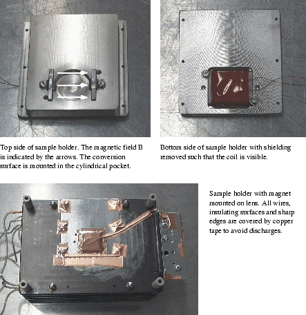
DC power for the magnet was provided using a circuit shown in Figure 6.4.
A 25 kHz sine signal from a external waveform generator was fed into a balanced class A push-pull power amplifier realized using two bipolar transistors to lower the source impedance from 50A complete shielding around rectifier, capacitor, and coil of the magnet should minimize the danger of discharges to the high voltage side of the electronics (Figure 6.5).
Unfortunately during the measurements discharges occurred destroying the diodes in the rectifier once. After replacement no influence of the magnet on the measurements could be found but it was later discovered that a discharge had also short-circuited the coil of the magnet towards ground rendering the magnet useless. No replacement was installed during the measurement session because of the high amount of work needed to make a new coil. Fortunately the background was low enough to make measurements without the magnet.March 2001 - Martin Wieser, Physikalisches Institut, University of Berne, Switzerland